pro 5000 install manual
Honeywell Pro 5000 Install Manual: A Comprehensive Plan
This manual details the installation of the Honeywell Pro 5000 thermostat, offering step-by-step guidance.
It covers everything from initial setup to advanced configurations, ensuring a smooth and efficient process.
Referencing resources like circuitlistniklas and diagramfixselah99 will aid in successful implementation.
The Honeywell Pro 5000 represents a significant advancement in home climate control technology, offering users a blend of precision, efficiency, and smart home integration. This thermostat series, including the FocusPro 5000, is designed for both professional installers and DIY enthusiasts seeking a reliable and feature-rich system. As evidenced by resources like circuitlistniklas and circuitparttim, the Pro 5000 boasts a user-friendly interface and compatibility with a wide range of heating and cooling systems.
This manual serves as a comprehensive guide to installing and configuring your Honeywell Pro 5000 thermostat. It will walk you through each stage of the process, from unpacking and verifying components to establishing a Wi-Fi connection and troubleshooting common issues. Understanding the system’s capabilities, as highlighted in various online manuals, is crucial for maximizing its benefits. Proper installation ensures optimal performance and longevity, delivering consistent comfort and energy savings.
Package Contents and Verification
Upon receiving your Honeywell Pro 5000, carefully inspect the package for any signs of damage during shipping. A complete package typically includes the thermostat display unit, a mounting baseplate, mounting screws and anchors, wire labels, and this installation manual. Referencing online resources like those found on circuitlistniklas can provide visual confirmation of expected components.
Before proceeding with installation, verify that all listed items are present. If anything is missing or appears damaged, immediately contact Honeywell support or your point of purchase. Accurate inventory is crucial to avoid delays and ensure a smooth installation process. Retain the original packaging for potential returns or warranty claims. Confirming the package contents now prevents complications later, guaranteeing a fully functional and properly installed system.
Safety Precautions
Prior to commencing installation of your Honeywell Pro 5000 thermostat, always disconnect power to your heating and cooling system at the breaker box. Failure to do so presents a serious risk of electrical shock. This is a critical safety measure. Work in a dry environment, avoiding any contact with water or moisture. If you are uncomfortable working with electrical wiring, consult a qualified HVAC technician.

Wear appropriate safety glasses to protect your eyes from debris. Be mindful of potential hazards when working with tools and ensure they are used correctly. Do not attempt to modify or repair any internal components of the thermostat. Improper installation can lead to system malfunction or safety hazards. Refer to the manual and resources like those available through circuitparttim for guidance. Prioritize safety throughout the entire installation process.
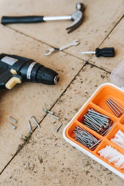
Tools Required for Installation
Successfully installing your Honeywell Pro 5000 thermostat requires a few essential tools. A Phillips head screwdriver is crucial for mounting the base and connecting wiring. A flathead screwdriver may also be needed for certain terminal connections. Wire strippers are essential for preparing the thermostat wires, ensuring clean and secure connections. A level will guarantee the thermostat is mounted straight, improving aesthetics and accuracy.
A voltage tester is highly recommended to verify power is off before working with wiring. Pliers can assist with bending and manipulating wires. A drill with appropriate drill bits may be necessary for mounting the base to certain wall types. Consider having a digital multimeter available for troubleshooting. Resources like those found on circuitlistniklas can offer visual aids. Having these tools readily available will streamline the installation process.
System Compatibility Check
Before beginning installation, verifying system compatibility is paramount for a successful Honeywell Pro 5000 setup. This thermostat generally supports standard 24V heating and cooling systems, including forced air, heat pump, and radiant heat. However, it’s crucial to confirm compatibility with millivolt systems or proprietary communication protocols.
Check your existing wiring to ensure you have a common (C) wire; the Pro 5000 often requires one for consistent power. Review your HVAC system’s documentation to identify wire functions. Resources like those referenced on circuitparttim can be helpful. Incompatibility can lead to malfunction or damage. If unsure, consult a qualified HVAC technician to assess your system and confirm compatibility before proceeding with the installation.

Wiring Diagram Overview
Understanding the wiring diagram is essential for a correct Honeywell Pro 5000 installation. The Pro 5000 utilizes a standard color-coding scheme, but variations exist. Typically, Red represents 24V power, White controls heating, Yellow controls cooling, Green is the common wire, and Black often serves as a fan control. However, always verify with your specific HVAC system’s wiring.
Refer to the detailed diagram included with your thermostat and cross-reference it with your existing wiring. Resources like those found on circuitlistniklas can provide visual aids. Incorrect wiring can damage the thermostat or your HVAC system. Double-check all connections before powering on the system. A clear understanding of the diagram prevents errors and ensures optimal performance.
Mounting the Thermostat Base
Properly mounting the thermostat base is crucial for a secure and functional installation. Begin by turning off power to your HVAC system at the breaker. Remove your old thermostat base, carefully noting the wire connections. Using the provided mounting screws, attach the Honeywell Pro 5000 baseplate to the wall, ensuring it’s level for accurate temperature readings.
Utilize a level to confirm proper alignment before fully tightening the screws. The base should be firmly secured to avoid vibrations. Feed the thermostat wires through the opening in the baseplate. Refer to online resources, such as those available through circuitparttim, for visual guidance. A stable base ensures reliable operation and prevents future issues.
Connecting the Wiring
Carefully connect the wiring to the Honeywell Pro 5000 base, referencing the wiring diagram in the manual. Ensure the power is OFF at the breaker before proceeding. Match each wire to its corresponding terminal, typically labeled with letters like R, C, W, Y, and G. Double-check connections to prevent shorts or malfunctions.
Securely tighten each screw terminal, but avoid over-tightening. Incorrect wiring can damage the thermostat or HVAC system. Resources like those found on circuitlistniklas can provide helpful visual aids. If unsure about any wire, consult a qualified HVAC technician. Proper wiring is essential for safe and reliable operation of your heating and cooling system.
8.1 Identifying Wire Colors and Functions

Accurately identifying wire colors and their functions is crucial for a successful Honeywell Pro 5000 installation. Common wire colors include Red (R) for 24V power, Green (G) for the fan, White (W) for heating, and Yellow (Y) for cooling. A Blue wire often represents the common (C) wire, essential for consistent power.
However, color coding can vary, so always verify with your existing thermostat’s wiring and the HVAC system’s documentation. Resources like those available through circuitparttim can offer guidance. Never assume a wire’s function based solely on color. Incorrect identification can lead to system malfunctions or damage. Label wires before disconnecting the old thermostat to avoid confusion.
8.2 Connecting Power Supply
Connecting the power supply correctly is vital for the Honeywell Pro 5000’s operation. Typically, the Red (R) wire provides 24V power. Ensure the HVAC system’s power is completely off at the breaker before proceeding. Connect the R wire to the designated ‘R’ terminal on the thermostat base.
If a common (C) wire is present, connect it to the ‘C’ terminal; this is increasingly important for reliable Wi-Fi connectivity and thermostat function. Resources like those found on circuitlistniklas emphasize the C-wire’s significance. A missing C-wire may require a C-wire adapter. Double-check all connections for tightness and security before restoring power. Improper connections can damage the thermostat or HVAC system.
8.3 Connecting Heating and Cooling Systems
Connecting the heating and cooling systems requires careful wire identification. The White (W) wire typically controls heating, while the Yellow (Y) wire manages cooling. Connect these to their corresponding terminals on the thermostat base. The Green (G) wire controls the fan; connect it to the ‘G’ terminal.

If you have a heat pump, additional wiring may be necessary, including an O/B wire for reversing valve control. Refer to the detailed wiring diagrams available on resources like diagramfixselah99 for specific configurations. Ensure wires are securely fastened to prevent loose connections. Incorrect wiring can lead to system malfunction or damage. Always verify the system type before making connections.
Attaching the Thermostat Display
Once the wiring is complete and verified, carefully attach the thermostat display to the mounted base. Align the display unit with the base, ensuring it sits flush and securely. Gently press the display onto the base until it clicks into place – a positive locking mechanism confirms a proper connection.
Avoid forcing the display, as this could damage the internal connectors. Double-check that all wires are tucked neatly inside the base before fully seating the display. Resources like circuitlistniklas provide visual guides for this step. A properly attached display is crucial for both functionality and aesthetic appeal. Ensure the screen is clearly visible and stable.
Initial Power-Up and System Check
After attaching the display, restore power to the thermostat at the breaker box. The Honeywell Pro 5000 should power on automatically, initiating a self-test sequence. Observe the display for any error messages or unusual behavior. Verify that the thermostat responds to basic commands, such as temperature adjustments.
Test both heating and cooling functions to confirm proper operation. Listen for the system components (furnace, air conditioner) to engage. If issues arise, immediately turn off the power and re-examine the wiring connections. Referencing manuals from circuitparttim can assist in diagnosing initial power-up problems. A successful system check is vital before proceeding to programming.
Programming Basic Settings
Once the system check is complete, configure the fundamental settings on your Honeywell Pro 5000. Begin by setting the correct date and time; accurate timekeeping is crucial for scheduling features. Next, define your preferred temperature units (Fahrenheit or Celsius). Configure the system type – specifying whether you have a conventional or heat pump system.
Establish temperature preferences for occupied and unoccupied periods. Explore the thermostat’s scheduling options to create a personalized comfort profile. Resources like those found on circuitlistniklas can provide detailed guidance on navigating the programming interface. Save your settings and verify they are correctly applied by observing the thermostat’s operation;
Wi-Fi Connection and Mobile App Setup
Connecting your Honeywell Pro 5000 to Wi-Fi unlocks remote control and advanced features. Initiate the connection process through the thermostat’s settings menu, selecting your home network and entering the password. Download the Honeywell Home app from your app store (iOS or Android). Create an account or log in if you already have one.
Within the app, follow the on-screen instructions to add your thermostat. The app will guide you through pairing the device, often involving scanning a QR code or entering a unique device ID. Once connected, you can adjust temperature settings, create schedules, and receive system alerts remotely. Refer to online resources for troubleshooting connection issues.
Troubleshooting Common Installation Issues
Even with careful installation, issues can arise. If the thermostat displays “No Power,” verify the C-wire connection is secure and the power supply is active. Incorrect temperature readings often stem from improper thermostat placement – avoid direct sunlight or drafts. Double-check wiring connections against the diagram; a swapped wire can cause malfunctions.
If the system doesn’t respond to commands, ensure the thermostat is compatible with your HVAC system. Consult the error code list within the manual or online resources to decipher specific issues. A weak Wi-Fi signal can disrupt connectivity; reposition your router or consider a Wi-Fi extender. Remember to always prioritize safety and disconnect power before inspecting wiring.
13.1 No Power to Thermostat

A complete lack of power is a common initial concern. First, confirm the circuit breaker supplying the HVAC system is not tripped. Next, meticulously inspect the C-wire (common wire) connection at both the thermostat and the furnace/air handler. A loose or disconnected C-wire is the most frequent culprit.
Verify the thermostat display is securely attached to the base, as a poor connection can interrupt power flow. If using a power extender kit, ensure it’s correctly installed and powered. Use a multimeter to test voltage at the thermostat terminals, confirming power is reaching the unit. If power is present at the terminals but the display remains blank, the thermostat itself may be faulty.
13.2 Incorrect Temperature Readings

Inaccurate temperature readings can stem from several sources. Begin by ensuring the thermostat isn’t directly exposed to sunlight, drafts, or heat-generating appliances. These external factors can significantly skew readings. Verify the thermostat is level; an unlevel installation can affect sensor accuracy.
Check the thermostat’s location settings within the programming menu. Confirm the correct zip code is entered, as this influences local weather data used for calibration. If the issue persists, perform a calibration adjustment within the settings, comparing the thermostat’s reading to a known accurate thermometer. A faulty temperature sensor within the thermostat itself may necessitate replacement.
Understanding Error Codes
The Honeywell Pro 5000 utilizes error codes to diagnose system issues. These codes, displayed on the thermostat screen, provide valuable clues for troubleshooting. A common code, “E1,” often indicates a loss of communication with the indoor or outdoor unit. “E2” typically signals a wiring fault, requiring a careful review of connections.
“E3” may point to a sensor malfunction, while “E4” often relates to power supply problems. Refer to the complete error code list within the installation manual or Honeywell’s support website for a detailed explanation of each code and recommended corrective actions. Ignoring error codes can lead to further system damage, so prompt investigation is crucial.

Advanced Configuration Options
The Honeywell Pro 5000 offers several advanced configuration options beyond basic scheduling. Users can customize temperature setbacks based on occupancy, utilizing geofencing through the mobile app for automated adjustments. Smart Recovery features learn heating/cooling patterns to pre-condition the home before scheduled events.
Advanced users can fine-tune system parameters like cycle rates and differential temperatures for optimal comfort and efficiency. The thermostat also supports humidity control, if equipped with a compatible humidifier or dehumidifier. Exploring these options, detailed in the full manual, allows for a highly personalized and energy-saving climate control experience. Remote access and control are key benefits.
Warranty Information and Support Resources
Honeywell provides a limited warranty for the Pro 5000 thermostat, typically covering defects in materials and workmanship for a specified period from the date of purchase. Please retain your proof of purchase for warranty claims. Detailed warranty terms and conditions are available in the product documentation and on the Honeywell Home website.
For technical support, troubleshooting assistance, and frequently asked questions, visit the Honeywell Home support portal. You can also contact Honeywell’s customer service team via phone or email. Online resources, including installation guides and video tutorials, are readily accessible. Referencing community forums and online resources like those found through searches can also provide helpful insights.
Need help setting up your Pro 5000? Find the official install manual & get up and running fast! Troubleshooting tips & expert advice inside.